1) Section of Oral Implantology, Department of Oral Rehabilitation, Fukuoka Dental College
2) Fukuoka Dental College Medical & Dental General Hospital Central Dental Laboratory
3) Section of Fixed Prosthodontics, Department of Oral Rehabilitation, Fukuoka Dental College
Implant superstructures, which connect multiple implants, particularly those using screw fixation, require high accuracy. When superstructures are fabricated using casting techniques, poor fitting caused by casting shrinkage of the alloy becomes an issue, and soldering has been used to correct the fit. The soldering process requires skills, and the accuracy of soldering is highly dependent on the practitioners’ techniques. The implementation of CAD/CAM technology has resolved the accuracy issue resulting from casting shrinkage, enabling reliable fabrication of superstructures with a good fit even for large frameworks. Since the materials used in CAD/CAM are mainly zirconia and non-precious metals, soldering cannot be used to correct the fit. Therefore, it is important to verify the accuracy of the working model when CAD/CAM are used to fabricate superstructures.1
One verification method of working-model accuracy uses a recording of the positional relationship made on an intraoral implant. This method involves the one screw test or alternate finger pressure test to verify that the intraoral implant positional relationship matches the implant positional relationship in a working model. Another method involves the intraoral one screw test using the recording of the positional relationship obtained from the model. These positional relationship recordings are called “verification jigs.”2,3
This study examined how the accuracy and operability of a verification jig are affected by the type of fixing resin used on the jig and by the sequence of fixation.
II. Materials and Methods
Master model
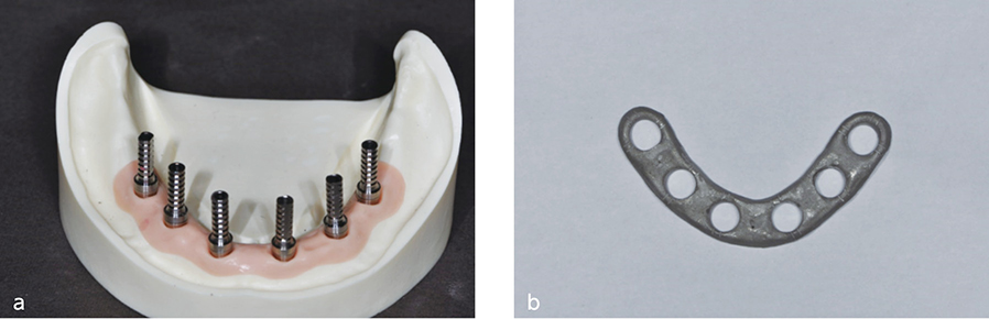
Six implant bodies (Branemark System MKIII, Nobel Biocare, Switzerland) were placed in an edentulous mandibular acrylic resin model, which was established as a master model. Screw-retained abutments (Multiunit Abutments, Nobel Biocare, Switzerland) were placed on these implants with 15 Ncm torque (Fig. 1).
Preparation of verification jig
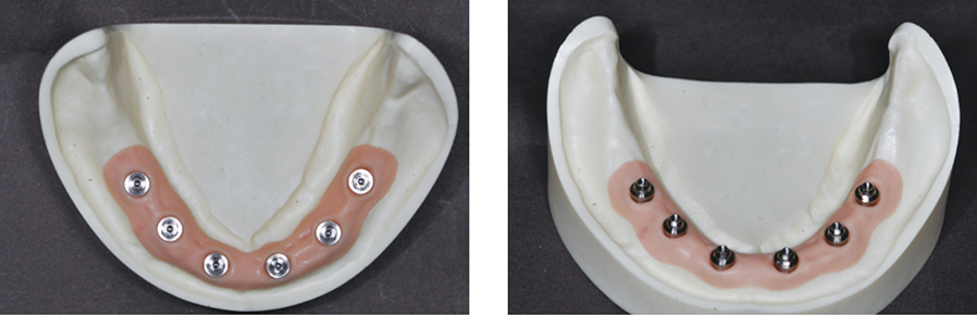
Titanium cylinders (Temporary Abutments, Nobel Biocare, Switzerland) were affixed to the six multiunit abutments using screws. A metal “ladder,” which was cast in cobalt-chrome alloy, was used to splint these temporary cylinders (Fig. 2). A gap of 1.5mm was established between the metal ladder and the temporary cylinders.
(Fig. 1) Master model after placement of multiunit abutments.(Fig. 2) a. Master model after placement of temporary cylinders. b. Metal ladder.
Fabrication of verification jig
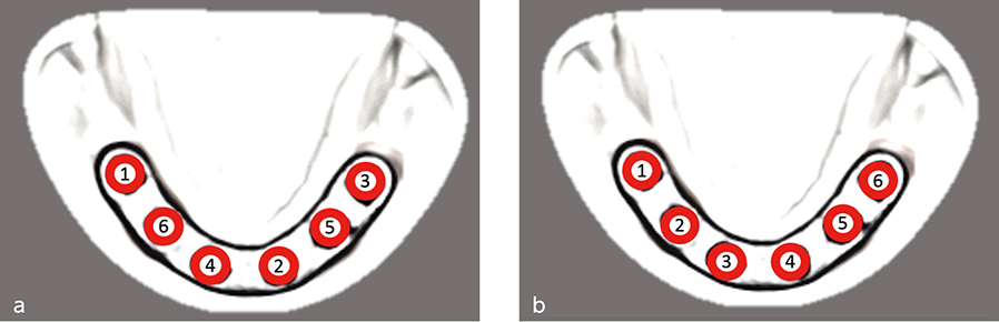
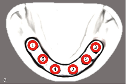
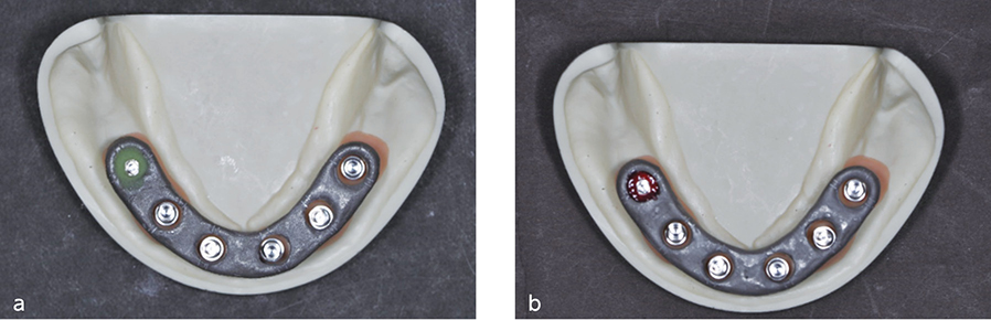
The right, most distal cylinder was affixed to the metal ladder (Fig. 3). The ladder was positioned so that the gap between the ladder and each cylinder was uniform among all the cylinders. The remaining cylinders were affixed to the ladder in the order indicated in Fig. 4a (pattern 1) or Fig. 4b (pattern 2).
One of the two resin types was used for fixation of the temporary cylinders to the ladder: a self-curing resin (Fixpeed, GC, Japan) or light-cured dental pattern resin (easyform, Detax, Germany). For Fixpeed, fixation was performed on one site at a time using the curing time in the product instructions. For easyform, fixation was performed by filling the gap between the metal ladder and the temporary cylinder, and then light curing was carried out from the top and bottom of the ladder for 20s and 10s, respectively.
The two resin types, Fixpeed and easyform, were used for fixation for pattern 1 and only easyform for pattern 2. The fixation process was repeated three times for each process and evaluated.
(Fig. 3) Metal ladder and cylinder-abutment were affixed at the right, most distal site.
a. Self-curing fixing resin. b. Light-cured dental pattern resin.(Fig. 4)
a. Sequence of fixation of cylinder-abutment to metal ladder (pattern 1).
b. Sequence of fixation of cylinder-abutment to metal ladder (pattern 2).
Measurement of working time
Measurement was taken on the time required for fixation using Fixpeed and easyform for pattern 1. Similarly, time was measured for fixation using easyform for pattern 2.
Evaluation of the accuracy of the fit
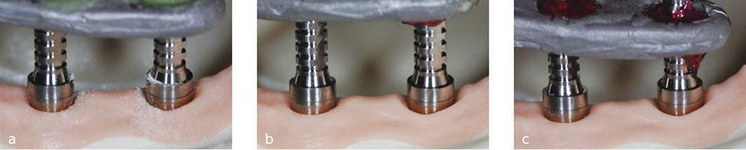
All abutment screws were removed after providing secure retention using resin, and then only the right, most distal abutment was refastened using 15 Ncm torque. The level of elevation (vertical misfit) was measured as the gap between each of the other multiunit abutments and temporary cylinder. The level of elevation was evaluated using a digital single-lens reflex camera (D5300, Nikon, Japan) to obtain a 1.5x-magnified image of a junction between a multiunit abutment and temporary cylinder. Then the image was enlarged by 30x on a screen for evaluation.
Statistical analysis
All values were calculated as an average of the three measured values. Statistical analysis was performed using SPSS version 19 (SPSS Inc., Chicago, IL). Student’s t-test was used to evaluate the difference between the two resin types in working time for verification jig fabrication (P<0.05).
III. Results
Working time for verification jig fabrication
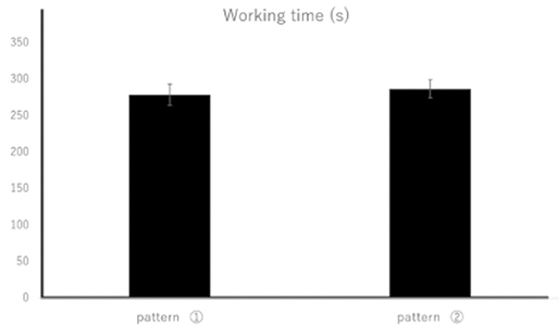
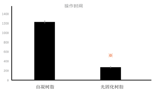
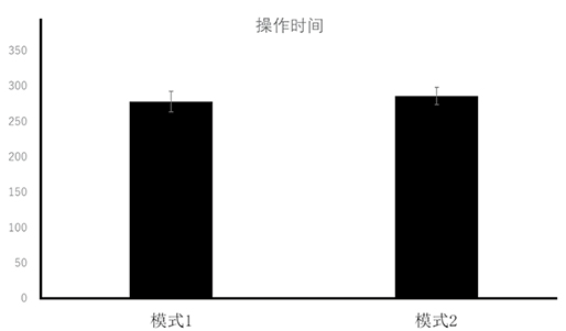
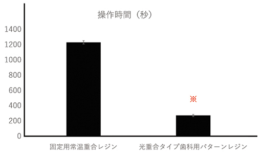
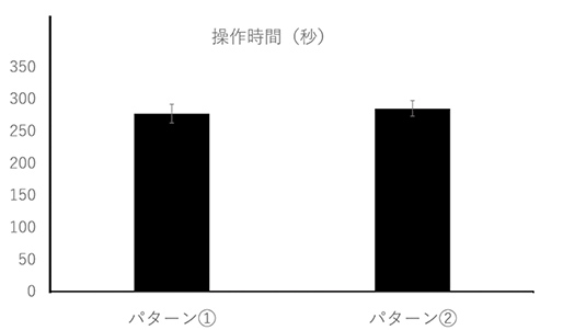
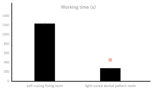
For pattern 1, the working time for verification jig fabrication was 1236.6±20.82s using self-curing fixing resin and 279.3±14.57s using light-cured dental pattern resin. For pattern 2, the working time was 287.0±12.17s using light-cured dental pattern resin. A significant difference was found in the working time between self-curing fixing resin and light-cured dental pattern resin (Fig. 5). No significant difference was found in the working time between pattern 1 using light-cured dental pattern resin and pattern 2 (Fig. 6).
(Fig. 5) Working time for verification jig fabrication using self-curing fixing resin and light-cured dental pattern resin.
※P<0.05(Fig. 6) Working time for verification jig fabrication using pattern 1 and 2 for fixation method.
Accuracy of the fit
No elevation (vertical misfit) was found between any multiunit abutment and temporary cylinder (Fig. 7).
(Fig. 7) The junction between the temporary cylinder and abutment at the left, most distal site, when the one screw test was performed at the right, most distal site of the verification jig.
a. Fixation using self-curing fixing resin for pattern 1.
b. Fixation using light-cured dental pattern resin for pattern 1.
c. Fixation using light-cured dental pattern resin for pattern 2.
IV. Discussion
For the treatment of multiple missing teeth, fabrication of titanium and zirconia frameworks using CAD/CAM is widely adopted, if screw-retained superstructures, which connect implants, are fabricated. Frameworks fabricated with CAD/CAM have a high accuracy of fit, and passive fit is more easily achieved by this method than the conventional method using casting.4 A good fit of screw-retained superstructures is an essential factor for long-term stability of superstructures. Lack of passive fit has been reported to result from distortion of impressions and models.5, 6 It is important to prevent such an error by using impression copings for open-tray impressions,7 by connecting impression copings,8 and by fabricating a verification jig to verify that the positional relationship in the working model is the same as the intraoral positional relationship of implants before fabricating superstructure with CAD/CAM.9-11 Hee-Kon Jang et al. fabricated master models, each of which had a different angle of divergence (0, 5, 10, 15, or 20 degrees) between two implant analogs. They made working models from each type of master model using an implant-level, open-tray, non-splinted coping impression technique. They fabricated metal frameworks on these five types of working models, tested the fit of the frameworks on the master models, and examined how changes in the angle between implants affected the framework fit. Their results indicate that the fit accuracy becomes unreliable at the angle of 20 degrees or larger. The findings indicate the importance of placing intermediate abutments and fabricating the verification jig to verify the fit of the working model to improve working-model accuracy when the inter-implant angle is 20 degrees or larger. In our study, six implant bodies were placed approximately parallel to one another in the master model. Even if they were not parallel, our results should be useful when the angles between implants were 20 degrees or less as screw-retained intermediate abutments were placed.
Our results showed that resin type did not affect the accuracy of the fit. Therefore, our results suggested that the uniform gap of 1.5mm between a metal ladder and temporary cylinders minimized the impact of resin shrinkage and was effective in achieving the accuracy of the fit of the verification jig.
The following methods using a verification jig have been widely used to verify the positional relationship of implant replicas in a model and the intraoral implant positional relationship. In one method, a verification jig is fabricated by connecting a metal ladder to temporary cylinders placed on implant replicas in a model. The one screw test is performed by placing this jig intraorally and tightening a screw at only one site. In another method, temporary cylinders are placed on intraoral implant bodies, and a metal ladder is connected to them, creating a verification jig. The alternate finger pressure test or one screw test is used to verify that the positional relationship in the model with the implant replicas matches the intraoral positional relationship. When a verification jig is fabricated intraorally, a shorter working time can help avoid a positional shift of the metal ladder and the impact from saliva, and thereby reducing human error. Additionally, the accuracy of the verification jig might be improved as working time can be shortened by the resin that easily fills the fixation site.
Self-curing fixing resin exhibits low polymerization shrinkage and, therefore, is used widely for recording intraoral implant positional relationships. Since self-curing resin requires several minutes to harden, working time will be long where fixation sites are numerous. Additionally, curing time varies as self-curing resin requires application of powder and liquid using brush-on techniques. Certain level of skills are needed for practitioners to accomplish this process using uniform amount of resin.
In our study, light-cured dental pattern resin was also used for the fixation process. Our findings showed that the light-cured resin required approximately one quarter of the time of the self-curing fixing resin in the fixation process of the verification jig.
We also evaluated the fit when light-cured dental pattern resin was used for fixation of temporary cylinders to the metal ladder and when self-cured fixing resin was used. No vertical misfit (rising) was observed in any of the samples, indicating a good fit. Therefore, our results showed that light-cured dental pattern resin with a short working time is highly useful in verification jig fabrication. When we evaluated different sequences for of the verification jig, we found that the sequence affected neither the accuracy of fit nor the working time. The results indicated that practitioners can determine the sequence of fixation based on the intraoral conditions, such as the amount of patient’s mouth opening and saliva.
In our future studies, we plan to examine methods to fabricate verification jigs with a metal ladder, which are easy to make using CAD/CAM, and methods to fabricate accurate verification jigs without a metal ladder.
V. Conclusion
No difference in accuracy of fit was found between a verification jig fabricated using light-cured dental pattern resin and that using self-cured fixing resin. However, the former requires shorter working time and, therefore, is more useful and has better operability. Our study also showed that fixation methods had no major effect on working time or accuracy of fit in verification jig fabrication.
References
Vitale ND, Tung F, Goldstein G.A technique to verify or correct analogue position and soft tissue profile on an implant working cast.J Prosthet Dent. 2009;102(3):137-40.
Jorge E De La Cruz , Paul D Funkenbusch, Carlo Ercoli, Mark E Moss, Gerald N Graser, Ross H Tallents. Verification jig for implant-supported prostheses: A comparison of standard impressions with verification jigs made of different materials. J Prosthet Dent. 2002;88(3):329-36.
Papaspyridakos P, Kim YJ, Finkelman M, El-Rafie K, Weber HP.Digital Evaluation of Three Splinting Materials Used to Fabricate Verification Jigs for Full-Arch Implant Prostheses: A Comparative Study.J Esthet Restor Dent. 2017;29(2):102-109.
J Y Kan, K Rungcharassaeng, K Bohsali, C J Goodacre, B R Lang. Clinical methods for evaluating implant framework fit. J Prosthet Dent. 1999 Jan;81(1):7-13.
Ercoli C, Geminiani A, Feng C, Lee H.The influence of verification jig on framework fit for nonsegmented fixed implant-supported complete denture.Clin Implant Dent Relat Res. 2012 May;14 :e188-95.
Yun-Jung Lee, Seong-Joo Heo, Jai-Young Koak, Seong-Kyun Kim. Accuracy of different impression techneques for internal-connection implants. Int J Oral Maxillofac Implants. 2009;24(5):823-30.
Tafti AF, Hatami M, Razavi F, Ebadian B.Comparison of the accuracy of open-tray and snap-on impression techniques of implants with different angulations.Dent Res J. 2019 12;16(6):413-420.
Papaspyridakos P, Benic GI, Hogsett VL, White GS, Lal K, Gallucci GO.Accuracy of implant casts generated with splinted and non-splinted impression techniques for edentulous patients: an optical scanning study.Clin Oral Implants Res. 2012;23(6):676-681.
Hee-Kon Jang, Sungtae Kim, June-Sung Shim, Keun-Woo Lee, Hong-Seok Moon. Accuracy of impressions for Internal-connection implant prostheses with various divergent angles. Int J Oral Maxillofac Implants. 2011;26(5):1011-5.
Baig MR.Multi-unit implant impression accuracy: A review of the literature. Quintessence Int. 2014 ;45(1):39-51
Buzayan MM, Yunus NB.Passive Fit in Screw Retained Multi-unit Implant Prosthesis Understanding and Achieving: A Review of the Literature. J Indian Prosthodont Soc. 2014;14(1):16-23.
1) Section of Oral Implantology, Department of Oral Rehabilitation, Fukuoka Dental College
2) Fukuoka Dental College Medical & Dental General Hospital Central Dental Laboratory
3) Section of Fixed Prosthodontics, Department of Oral Rehabilitation, Fukuoka Dental College
将六个种植体(Branemark System MKIII, Nobel Biocare, Switzerland)植入下颌无牙颌丙烯酸树脂模型作为主模型.用15N・cm的扭矩将螺丝固位复合基台(Multiunit Abutments, Nobel Biocare, Switzerland)固定在这些种植体上(图1).
定位夹板的准备
用螺丝将钛临时基台(Temporary Abutments, Nobel Biocare, Switzerland)固定在六个复合基台上,用钴铬合金铸造一个金属导板作为夹板固定这些临时基台(图2).在金属导板与临时基台之间设置1.5mm的间隙.
Vitale ND, Tung F, Goldstein G.A technique to verify or correct analogue position and soft tissue profile on an implant working cast.J Prosthet Dent. 2009;102(3):137-40.
Jorge E De La Cruz , Paul D Funkenbusch, Carlo Ercoli, Mark E Moss, Gerald N Graser, Ross H Tallents. Verification jig for implant-supported prostheses: A comparison of standard impressions with verification jigs made of different materials. J Prosthet Dent. 2002;88(3):329-36.
Papaspyridakos P, Kim YJ, Finkelman M, El-Rafie K, Weber HP.Digital Evaluation of Three Splinting Materials Used to Fabricate Verification Jigs for Full-Arch Implant Prostheses: A Comparative Study.J Esthet Restor Dent. 2017;29(2):102-109.
J Y Kan, K Rungcharassaeng, K Bohsali, C J Goodacre, B R Lang. Clinical methods for evaluating implant framework fit. J Prosthet Dent. 1999 Jan;81(1):7-13.
Ercoli C, Geminiani A, Feng C, Lee H.The influence of verification jig on framework fit for nonsegmented fixed implant-supported complete denture.Clin Implant Dent Relat Res. 2012 May;14 :e188-95.
Yun-Jung Lee, Seong-Joo Heo, Jai-Young Koak, Seong-Kyun Kim. Accuracy of different impression techneques for internal-connection implants. Int J Oral Maxillofac Implants. 2009;24(5):823-30.
Tafti AF, Hatami M, Razavi F, Ebadian B.Comparison of the accuracy of open-tray and snap-on impression techniques of implants with different angulations.Dent Res J. 2019 12;16(6):413-420.
Papaspyridakos P, Benic GI, Hogsett VL, White GS, Lal K, Gallucci GO.Accuracy of implant casts generated with splinted and non-splinted impression techniques for edentulous patients: an optical scanning study.Clin Oral Implants Res. 2012;23(6):676-681.
Hee-Kon Jang, Sungtae Kim, June-Sung Shim, Keun-Woo Lee, Hong-Seok Moon. Accuracy of impressions for Internal-connection implant prostheses with various divergent angles. Int J Oral Maxillofac Implants. 2011;26(5):1011-5.
Baig MR.Multi-unit implant impression accuracy: A review of the literature. Quintessence Int. 2014 ;45(1):39-51
Buzayan MM, Yunus NB.Passive Fit in Screw Retained Multi-unit Implant Prosthesis Understanding and Achieving: A Review of the Literature. J Indian Prosthodont Soc. 2014;14(1):16-23.
1) Section of Oral Implantology, Department of Oral Rehabilitation, Fukuoka Dental College
2) Fukuoka Dental College Medical & Dental General Hospital Central Dental Laboratory
3) Section of Fixed Prosthodontics, Department of Oral Rehabilitation, Fukuoka Dental College
Vitale ND, Tung F, Goldstein G.A technique to verify or correct analogue position and soft tissue profile on an implant working cast.J Prosthet Dent. 2009;102(3):137-40.
Jorge E De La Cruz , Paul D Funkenbusch, Carlo Ercoli, Mark E Moss, Gerald N Graser, Ross H Tallents. Verification jig for implant-supported prostheses: A comparison of standard impressions with verification jigs made of different materials. J Prosthet Dent. 2002;88(3):329-36.
Papaspyridakos P, Kim YJ, Finkelman M, El-Rafie K, Weber HP.Digital Evaluation of Three Splinting Materials Used to Fabricate Verification Jigs for Full-Arch Implant Prostheses: A Comparative Study.J Esthet Restor Dent. 2017;29(2):102-109.
J Y Kan, K Rungcharassaeng, K Bohsali, C J Goodacre, B R Lang. Clinical methods for evaluating implant framework fit. J Prosthet Dent. 1999 Jan;81(1):7-13.
Ercoli C, Geminiani A, Feng C, Lee H.The influence of verification jig on framework fit for nonsegmented fixed implant-supported complete denture.Clin Implant Dent Relat Res. 2012 May;14 :e188-95.
Yun-Jung Lee, Seong-Joo Heo, Jai-Young Koak, Seong-Kyun Kim. Accuracy of different impression techneques for internal-connection implants. Int J Oral Maxillofac Implants. 2009;24(5):823-30.
Tafti AF, Hatami M, Razavi F, Ebadian B.Comparison of the accuracy of open-tray and snap-on impression techniques of implants with different angulations.Dent Res J. 2019 12;16(6):413-420.
Papaspyridakos P, Benic GI, Hogsett VL, White GS, Lal K, Gallucci GO.Accuracy of implant casts generated with splinted and non-splinted impression techniques for edentulous patients: an optical scanning study.Clin Oral Implants Res. 2012;23(6):676-681.
Hee-Kon Jang, Sungtae Kim, June-Sung Shim, Keun-Woo Lee, Hong-Seok Moon. Accuracy of impressions for Internal-connection implant prostheses with various divergent angles. Int J Oral Maxillofac Implants. 2011;26(5):1011-5.
Baig MR.Multi-unit implant impression accuracy: A review of the literature. Quintessence Int. 2014 ;45(1):39-51
Buzayan MM, Yunus NB.Passive Fit in Screw Retained Multi-unit Implant Prosthesis Understanding and Achieving: A Review of the Literature. J Indian Prosthodont Soc. 2014;14(1):16-23.
1) Sección de Implantología Oral, Departamento de Rehabilitación Oral, Facultad de Odontología de Fukuoka
2) Fukuoka Dental College Medical & Dental Hospital General Laboratorio Dental Central
3) Sección de Prostodoncia Fija, Departamento de Rehabilitación Oral, Facultad de Odontología de Fukuoka
Traducción al Español: Dr. Fernando Andres Colindre
Palabras clave: implantes dentales, plantilla de verificación, multiunidad, selresina de fijación fotopolimerizable, resina de patrón dental fotopolimerizable
I. Introducción
Las superestructuras de implantes, que conectan varios implantes, en particular los que utilizan fijación con tornillos, requieren una alta precisión. Cuando las superestructuras se fabrican utilizando técnicas de fundición, el mal ajuste causado por la contracción de la aleación en la fundición se convierte en un problema, y se ha utilizado soldadura para corregir el ajuste. El proceso de soldadura requiere habilidades y la precisión de la soldadura depende en gran medida de las técnicas de los profesionales. La implementación de la tecnología CAD / CAM ha resuelto el problema de precisión resultante de la contracción de la fundición, lo que permite la fabricación confiable de superestructuras con un buen ajuste incluso para estructuras grandes. Dado que los materiales utilizados en CAD / CAM son principalmente zirconia y metales no preciosos, no se puede utilizar soldadura para corregir el ajuste. Por lo tanto, es importante verificar la precisión del modelo de trabajo cuando se usa CAD/CAM para fabricar superestructuras.1
Un método de verificación de la precisión del modelo de trabajo utiliza un registro de la relación posicional realizada en un implante intraoral. Este método implica la prueba de un tornillo o la prueba de presión digital alternativa para verificar que la relación posicional del implante intraoral coincide con la relación posicional del implante en un modelo de trabajo. Otro método implica la prueba de un tornillo intraoral utilizando el registro de la relación posicional obtenida del modelo. Estos registros de relaciones posicionales se denominan "plantillas de verificación".2,3
Este estudio examinó cómo la precisión y la operatividad de una plantilla de verificación se ven afectadas por el tipo de resina de fijación utilizada en la plantilla y por la secuencia de fijación.
II. Materiales y métodos
Modelo maestro
Se colocaron seis implantes (Branemark System MKIII, Nobel Biocare, Suiza) en un modelo de resina acrílica mandibular desdentado, que se estableció como modelo maestro. Sobre estos implantes se colocaron pilares atornillados (Multiunit Abutments, Nobel Biocare, Suiza) con un torque de 15 Ncm (Fig. 1).
Preparación de la plantilla de verificación
Los cilindros de titanio (pilares provisionales, Nobel Biocare, Suiza) se fijaron a los seis pilares de múltiples unidades mediante tornillos. Se usó una “estructura” de metal, que se fundió en una aleación de cromo-cobalto, para ferulizar estos cilindros temporales (Fig. 2). Se estableció un espacio de 1,5 mm entre la estructura metálica y los cilindros provisionales.
(Fig. 1) Modelo maestro tras la colocación de pilares multiunitarios.(Fig. 2) a. Modelo maestro después de la colocación de cilindros provisionales. segundo. b. Escalera de metal.
Fabricación de plantilla de verificación
El cilindro derecho, más distal, se fijó a la estructura de metal (Fig. 3). La estructura se colocó de modo que el espacio entre ésta y cada cilindro fuera uniforme entre todos los cilindros. Los cilindros restantes se fijaron a la estructura en el orden indicado en la Fig. 4a (patrón 1) o en la Fig. 4b (patrón 2).
Se utilizó uno de los dos tipos de resina para la fijación de los cilindros provisionales a la estructura: una resina autopolimerizable (Fixpeed, GC, Japón) o una resina de patrón dental fotopolimerizable (easyform, Detax, Alemania). Para Fixpeed, la fijación se realizó en un sitio a la vez utilizando el tiempo de curado en las instrucciones del producto. Para facilitar la forma, la fijación se realizó llenando el espacio entre la estructura de metal y el cilindro temporal, y luego se llevó a cabo la fotopolimerización desde la parte superior e inferior de la estructura durante 20 seg. y 10 seg, respectivamente.
Los dos tipos de resina, Fixpeed y easyform, se utilizaron para la fijación del patrón 1 y solo easyform para el patrón 2. El proceso de fijación se repitió tres veces para cada proceso y se evaluó.
(Fig. 3) Se colocaron una escalera de metal y un cilindro-pilar en el sitio más distal derecho.
a. Resina fijadora autopolimerizable. segundo. b. Resina de patrón dental fotopolimerizable.(Fig. 4)
a. Secuencia de fijación cilindro-pilar a escalera metálica (patrón 1).
b. Segundo. Secuencia de fijación cilindro-pilar a escalera metálica (patrón 2).
Medida del tiempo de trabajo
Se midió el tiempo necesario para la fijación con Fixpeed y easyform para el patrón 1. De manera similar, se midió el tiempo de fijación con easyform para el patrón 2.
Evaluación de la precisión del ajuste
Todos los tornillos del pilar se retiraron después de proporcionar una retención segura con resina, y luego solo se volvió a sujetar el pilar derecho, la mayoría de los pilares distales, con un torque de 15 Ncm. El nivel de elevación (desajuste vertical) se midió como el espacio entre cada uno de los otros pilares de múltiples unidades y el cilindro temporal. El nivel de elevación se evaluó utilizando una cámara réflex digital de un solo objetivo (D5300, Nikon, Japón) para obtener una imagen ampliada a 1,5 aumentos de una unión entre un pilar de múltiples unidades y un cilindro temporal. Luego, la imagen se amplió 30x en una pantalla para su evaluación.
Análisis Estadístico
Todos los valores se calcularon como un promedio de los tres valores medidos. El análisis estadístico se realizó utilizando SPSS versión 19 (SPSS Inc., Chicago, IL). Se utilizó la prueba t de Student para evaluar la diferencia entre los dos tipos de resina en el tiempo de trabajo para la fabricación de la plantilla de verificación (P<0,05).
III. Resultados
Tiempo de trabajo para la fabricación de la plantilla de verificación
Para el patrón 1, el tiempo de trabajo para la fabricación de la plantilla de verificación fue de 1236,6 ± 20,82 s utilizando resina de fijación autopolimerizable y 279,3 ± 14,57 s utilizando resina de patrón dental fotopolimerizable. Para el patrón 2, el tiempo de trabajo fue de 287,0 ± 12,17 s utilizando resina de patrón dental fotopolimerizable. Se encontró una diferencia significativa en el tiempo de trabajo entre la resina fijadora autopolimerizable y la resina de patrón dental fotopolimerizable (Fig. 5). No se encontraron diferencias significativas en el tiempo de trabajo entre el patrón 1 que usa resina de patrón dental fotopolimerizable y el patrón 2 (Fig. 6).
(Fig. 5) Tiempo de trabajo para la fabricación de la plantilla de verificación utilizando resina de fijación autopolimerizable y resina de patrón dental fotopolimerizable.※P<0.05(Fig. 6) Tiempo de trabajo para la fabricación de la plantilla de verificación utilizando el patrón 1 y 2 para el método de fijación.
Precisión del ajuste
No se encontró elevación (desajuste vertical) entre ningún pilar multiuni y el cilindro temporal (Fig. 7).
(Fig. 7) La unión entre el cilindro temporal y el pilar en el sitio más distal izquierdo, cuando se realizó la prueba de un tornillo en el sitio más distal derecho de la plantilla de verificación.
a. Fijación con resina de fijación autopolimerizable para el patrón 1.
b. Segundo. Fijación con resina de patrón dental fotopolimerizable para el patrón 1.
c. Fijación con resina de patrón dental fotopolimerizable para el patrón 2.
IV. Discusión
Para el tratamiento de múltiples dientes faltantes, se adopta ampliamente la fabricación de estructuras de titanio y zirconia utilizando CAD / CAM, si se fabrican superestructuras atornilladas, que conectan implantes. Las estructuras fabricadas con CAD / CAM tienen una alta precisión de ajuste y el ajuste pasivo se logra más fácilmente con este método que con el método convencional que utiliza fundición.4 Un buen ajuste de las superestructuras atornilladas es un factor esencial para la estabilidad a largo plazo de superestructuras. Se ha informado que la falta de ajuste pasivo es el resultado de la distorsión de las impresiones y los modelos.5, 6 Es importante prevenir este error utilizando cofias de impresión para impresiones de cubeta abierta,7 conectando cofias de impresión,8 y mediante la fabricación de una plantilla de verificación para verificar que la relación posicional en el modelo de trabajo es la misma que la relación posicional intraoral de los implantes antes de fabricar la superestructura con CAD / CAM.9-11 Hee-Kon Jang et al. Fabricaron modelos maestros, cada uno de los cuales tenía un ángulo de divergencia diferente (0, 5, 10, 15 o 20 grados) entre dos análogos de implantes. Hicieron modelos de trabajo de cada tipo de modelo maestro utilizando una técnica de impresión de cofia no ferulizada, cubeta abierta a nivel de implante. Fabricaron estructuras metálicas en estos cinco tipos de modelos de trabajo, probaron el ajuste de las estructuras en los modelos maestros y examinaron cómo los cambios en el ángulo entre los implantes afectaban el ajuste de la estructura. Sus resultados indican que la precisión de ajuste se vuelve poco confiable en un ángulo de 20 grados o más. Los hallazgos indican la importancia de colocar pilares intermedios y fabricar la plantilla de verificación para verificar el ajuste del modelo de trabajo para mejorar la precisión del modelo de trabajo cuando el ángulo entre implantes es de 20 grados o más. En nuestro estudio, se colocaron seis cuerpos de implantes aproximadamente paralelos entre sí en el modelo maestro. Incluso si no fueran paralelos, nuestros resultados deberían ser útiles cuando los ángulos entre los implantes fueran de 20 grados o menos cuando se colocaron pilares intermedios atornillados.
Nuestros resultados mostraron que el tipo de resina no afectó la precisión del ajuste. Por lo tanto, nuestros resultados sugirieron que el espacio uniforme de 1,5 mm entre una estructura de metal y cilindros temporales minimizó el impacto de la contracción de la resina y fue eficaz para lograrla precisión del ajuste de la plantilla de verificación.
Los siguientes métodos que utilizan una plantilla de verificación se han utilizado ampliamente para verificar la relación posicional de las réplicas de implantes en un modelo y la relación posicional del implante intraoral. En un método, se fabrica una plantilla de verificación conectando una estructura de metal a cilindros temporales colocados en réplicas de implantes en un modelo. La prueba de un tornillo se realiza colocando esta plantilla intraoralmente y apretando un tornillo en un solo lugar. En otro método, se colocan cilindros temporales en cuerpos de implantes intraorales, y se les conecta una escalera de metal, creando una plantilla de verificación. La APrueba de presión digital alternativa o la prueba de un tornillo se usa para verificar que la relación posicional en el modelo con las réplicas del implante coincide con la relación posicional intraoral. Cuando se fabrica una plantilla de verificación intraoralmente, un tiempo de trabajo más corto puede ayudar a evitar un cambio de posición de la estructura de metal y el impacto de la saliva, reduciendo así el error humano. Además, la precisión de la plantilla de verificación podría mejorarse, ya que la resina puede acortar el tiempo de trabajo que llena fácilmente el sitio de fijación.
La resina de fijación autopolimerizable exhibe una contracción de polimerización baja y, por lo tanto, se usa ampliamente para registrar relaciones posicionales de implantes intraorales. Dado que la resina autopolimerizable requiere varios minutos para endurecerse, el tiempo de trabajo será prolongado cuando los lugares de fijación sean numerosos. Además, el tiempo de curado varía ya que la resina autopolimerizable requiere la aplicación de polvo y líquido mediante técnicas de brocha. Se necesita cierto nivel de habilidades para que los profesionales logren este proceso utilizando una cantidad uniforme de resina.
En nuestro estudio, también se utilizó resina de patrón dental fotopolimerizable para el proceso de fijación. Nuestros hallazgos mostraron que la resina fotopolimerizable requirió aproximadamente una cuarta parte del tiempo de la resina de fijación autopolimerizable en el proceso de fijación de la plantilla de verificación.
También evaluamos el ajuste cuando se usó resina de patrón dental fotopolimerizable para la fijación de cilindros temporales a la estructura de metal y cuando se usó resina de fijación autopolimerizable. No se observó desajuste vertical (ascendente) en ninguna de las muestras, lo que indica un buen ajuste. Por lo tanto, nuestros resultados mostraron que la resina de patrón dental fotopolimerizable con un tiempo de trabajo corto es muy útil en la fabricación de plantillas de verificación. Cuando evaluamos diferentes secuencias de la plantilla de verificación, encontramos que la secuencia no afectaba ni la precisión del ajuste ni el tiempo de trabajo. Los resultados indicaron que los clínicos pueden determinar la secuencia de fijación en función de las condiciones intraorales, como la cantidad de apertura de la boca del paciente y la saliva.
En nuestros estudios futuros, planeamos examinar métodos para fabricar plantillas de verificación con una estructuraa de metal, que son fáciles de hacer usando CAD / CAM, y métodos para fabricar plantillas de verificación precisas sin una estructura de metal.
V. Conclusión
No se encontró ninguna diferencia en la precisión de ajuste entre una plantilla de verificación fabricada con resina de patrón dental fotopolimerizable y la que utiliza resina de fijación autopolimerizable. Sin embargo, el primero requiere un tiempo de trabajo más corto y, por lo tanto, es más útil y tiene una mejor operatividad. Nuestro estudio también mostró que los métodos de fijación no tenían un efecto importante sobre el tiempo de trabajo o la precisión del ajuste en la fabricación de la plantilla de verificación.
Referencias
Técnica Vitale ND, Tung F, Goldstein GA para verificar o corregir la posición análoga y el perfil del tejido blando en un modelo de trabajo de implante J Prosthet Dent. 2009; 102 (3): 137-40.
Jorge E De La Cruz, Paul D Funkenbusch, Carlo Ercoli, Mark E Moss, Gerald N Graser, Ross H Tallents. Plantilla de verificación para prótesis implantosoportadas: comparación de impresiones estándar con plantillas de verificación hechas de diferentes materiales. J Prosthet Dent. 2002; 88 (3): 329-36.
Papaspyridakos P, Kim YJ, Finkelman M, El-Rafie K, Weber HP. Evaluación digital de tres materiales de ferulización utilizados para fabricar plantillas de verificación para prótesis de implantes de arco completo: un estudio comparativo. J Esthet Restor Dent. 2017; 29 (2): 102-109.
JY Kan, K Rungcharassaeng, K Bohsali, CJ Goodacre, BR Lang. Métodos clínicos para evaluar el ajuste de la estructura del implante. J Prosthet Dent. Enero de 1999; 81 (1): 7-13.
Ercoli C, Geminiani A, Feng C, Lee H. Influencia de la plantilla de verificación en el ajuste de la estructura para dentaduras postizas completas no segmentadas fijas implantosoportadas Clin Implant Dent Relat Res. 2012 mayo; 14: e188-95.
Yun-Jung Lee, Seong-Joo Heo, Jai-Young Koak, Seong-Kyun Kim. Precisión de diferentes técnicas de impresión para implantes de conexión interna. Implantes Int J Oral Maxillofac. 2009; 24 (5): 823-30.
Tafti AF, Hatami M, Razavi F, Ebadian B. Comparación de la precisión de las técnicas de impresión de cubeta abierta y snap-on de implantes con diferentes angulaciones Dent Res J. 2019 12; 16 (6): 413-420.
Papaspyridakos P, Benic GI, Hogsett VL, White GS, Lal K, Gallucci GO. Precisión de modelos de implantes generados con técnicas de impresión ferulizadas y no ferulizadas para pacientes edéntulos: un estudio de escaneo óptico Clin Oral Implants Res. 2012; 23 (6): 676-681.
Hee-Kon Jang, Sungtae Kim, June-Sung Shim, Keun-Woo Lee, Hong-Seok Moon. Precisión de impresiones para prótesis de implantes de conexión interna con varios ángulos divergentes. Implantes Int J Oral Maxillofac. 2011; 26 (5): 1011-5.
Precisión de impresión de implantes múltiples de Baig MR: una revisión de la literatura. Quintaesencia Int. 2014; 45 (1): 39-51
Buzayan MM, Yunus NB. Ajuste pasivo en prótesis de implantes de unidades múltiples retenidas por tornillos Comprensión y logro: una revisión de la literatura. J Indian Prosthodont Soc. 2014; 14 (1): 16-23.